Jack Lichterman
WOrks
in
progress
Capstone Project (complete)
2020-2021

Elevator pitch video
This video is a short summary of our project
planning
9/21/20
Our group has decided to work to improve electric generation in terms of cost, water usage, and carbon emissions. We have researched possible experts to reach out to, associations to market toward, and a general problem statement on the necessity of improvement to electric generation.
10/30/20
We have specified our project to the heat to kinetic energy transfer (boiling of water). We researched similar solutions and have found a few that have given us some ideas for our potential solution. We are reaching out to potential experts and associations for both mentorship and to answer surveys we have created in order to support justification of our project.
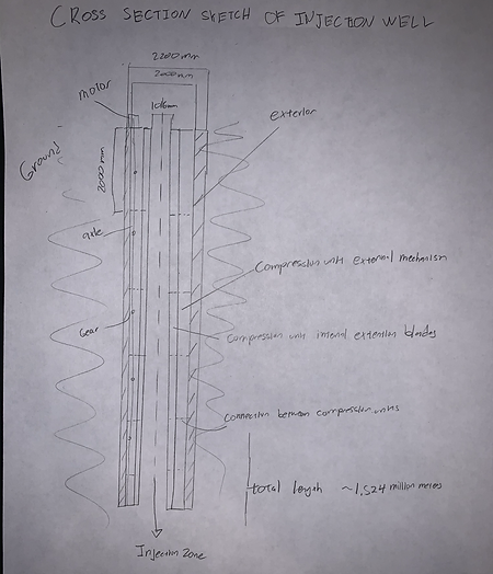
The Cross section here shows the modifications with respect to the injection well of a Geothermal Power Plant. There is an exterior casing and the interior compression units, which the water will run through.
Designing
12/9/20
Our initial solution was to replace the water in a steam turbine with some room temperature solid ( Sulphur was our choice ). However, after doing research on the efficiency of this, we found that this idea was actual less efficient at exchanging heat energy than water.
After this, we discussed with our mentor what kind of products the market might have interest in. According to him, the biggest issue in the industry is changing electrical demand.
Side view and complete view
To determine how to best approach this problem, our team researched different types of steam electric generation methods. We chose to move forward focusing on geothermal powerplants because of the renewable energy production methods, it is one of the few that has an input that is determined by the operator.
Finally, we developed our solution. A funnel type device combined with a camera lens-like control valve.
Side View

The Cross section here shows the modifications with respect to the injection well of a Geothermal Power Plant. There is an exterior casing and the interior compression units, which the water will run through.

This view shows the well and the control as cylindrical shapes.
Compression Unit

The Compression unit will open and close along the interior. This will force the water pressure to increase, while the unit is driven by an attached gear which can be connected to an axle.
We are now researching in order to determine what size and strength will be required of the design.
Design results
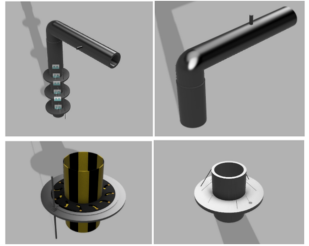
Below is the complete assembly of all parts of the design. Note that while there are three exteriors attached, a working model would have several hundred.

This image above show the modeled and drawn compression unit. There were many changes made from the initial sketch design. First of all, the shape. The initial unit was a cylinder. Now it has more of a top shape. After creating the design, we realized that the exterior mechanism of the iris took up much more space than we had initially thought.
There is also a change in volume. In the initial design, the mechanism of the iris was going to fill the entire height that the blades would be, making a cylinder. We changed the design for a thinner mechanism to save material. This left long extrusions from the blades to fill the space where more mechanism would have been. The pure iris mechanism can be seen here.
The Gate valve we modeled is almost identical to the one we designed. The only difference is that we added a corner pipe and vertical pipe in order for the pipe to connect to the injection well.
The fourth major component is the exterior. Notice that it looks quite different from the initial design (a cylinder). This is because the mechanism of the iris took much more space than we had thought it would (modifications and actual iris mechanism combined). Rather than increase the size of the exterior, we realized that a more fitted shape would be more efficient. This reduces the materials use, weight, and cost of the potential larger cylinder. It also more efficiently uses the space available (with a cylinder, most of it would be empty) and provides better support for each individual compression unit, allowing them a fitted space to sit.
On both the upper and lower half, we included support beams. These would help the extruded portion stay upright. There is also a small hole in the extrusion. This is where the long axle would run through.

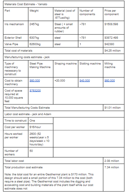
This is the cost estimate for constructing the design. The size (diameter and depth) are both dependent on the given circumstance of Geothermal Energy. The dimensions that have been used here are on the upper end of what could be demanded ( a geothermal well could go from 36” diameter to 4” and could have a depth of greater than 5000ft. The Manufacturing costs and Labor costs estimates are extremely rough. In practice, these would likely be combined by the manufacturing company/agent who is contracted to construct it.
Preparing for production and Redesigns
We have prepared to build a small scale working model of our design.
- Resizing. We have reduced the size of our model by a factor of 20
- Material. We have replaced the steel material of our solution with PLA plastic
- Replacing. To reduce the cost of plastic, we have replaced PLA pipe-like components with PVC pipes.
Mentor redesigns
After mentor advisement, we have made a few changes to our iris model. In order to provide pressure and pump the water, the interior of the blades will be slanted. Photo is shown later on.
1/26/21
We have developed a process for building our model as well as where we are finding the parts for the design.
- 3D printing. Many parts are being 3D printed and parts that are meant to be rigid against one another have been combined.
- Vex parts. For our axle and motor which provide the rotation we are planning to use vex parts which we will get from school.
- construction. Uses gorilla glue, wood pieces, and plumbers tape to hold up and affix the design while it is and after it is constructed.
Testing
We are planning to test the viability of our model by first seeing if it can run water in a loop.
We will be monitoring watertight capabilities, gear strength, and motor strength.
We will also be comparing the pumping capabilities of our design versus a competitor model of similar scale